Hi there!
In our control room series we now start to battle the early reflections.
This is done by the use of early reflection absorbers that need to be able to absorb frequencies as broad as possible. Therefore, one should not use any reflecting materials like foils in front of such elements as these would reflect higher frequencies.
In order to prevent the release of fibers I decided to leave mineral wool aside and used Caruso Isobond WLG35 instead. Isobond is a material that’s woven out of polyester fibers and that looks and feels similar to a mattress. With a specific flow resistance of 12 kPa*s/m^2 Isobond WLG35 is ideal for a thinner early reflection absorber. Moreover, it’s completely free of chemical additives. For each of my two absorbers I used 3 pieces of Isobond with a thickness of 10cm, leading to a total dimension of 1 x 1.5m of absorbent material mounted inside of a wooden frame that had been previously mounted directly to the wall. At the end everything has been covered with the same fabric as the bass absorbers in the previous articles.
The correct points to mount these early or rather first reflection absorbers are on the side-walls in between your (near-field) monitors and listening sweetspot, such that they cover the area of first reflections on the walls, see e.g., the sketch here.
And this is how a finished absorber looks like.

Finished early reflection absorber on one wall of my control room
Furthermore, I needed a place for my clients to sit down and relax when listening to mixes or discussing recordings. I opted for a big fabric couch and placed that at the back wall of the control room. As it is 240cm long and 100cm deep I expected that it would have quit some impact on the room acoustics, even for lower frequencies.

Big couch for clients to sit down and listen to mixes
So let’s see how the measurements look like after that changes.
When taking a closer look at the frequency response graph we see that some of the bigger minima and maxima have been smoothed out quiet a bit as compared to the graph in Building a proper control room – recovery of mid and high frequency response by the use of wooden boards. Most noticeably the pronounced dip at 90Hz and the maximum at around 130Hz. However, we also see a new dip at approx. 270Hz and a second one that appeared between 100 and 200Hz. No win without loss, you know. We will see what happens to the frequency response when we proceed in the construction process.

Frequency response with ER absorbers and couch installed
The EDT curve, waterfall and spectrogram show a significant improvement now. You can clearly see that we succeeded in bringing down the Early Decay Time to below approx. 300ms nearly everywhere in the spectrum, apart from the region below 90Hz, which is due to room modes obviously. But even there it is down to 450ms already, which is a really good value for such a small room.

EDT curve with ER absorbers and couch installed
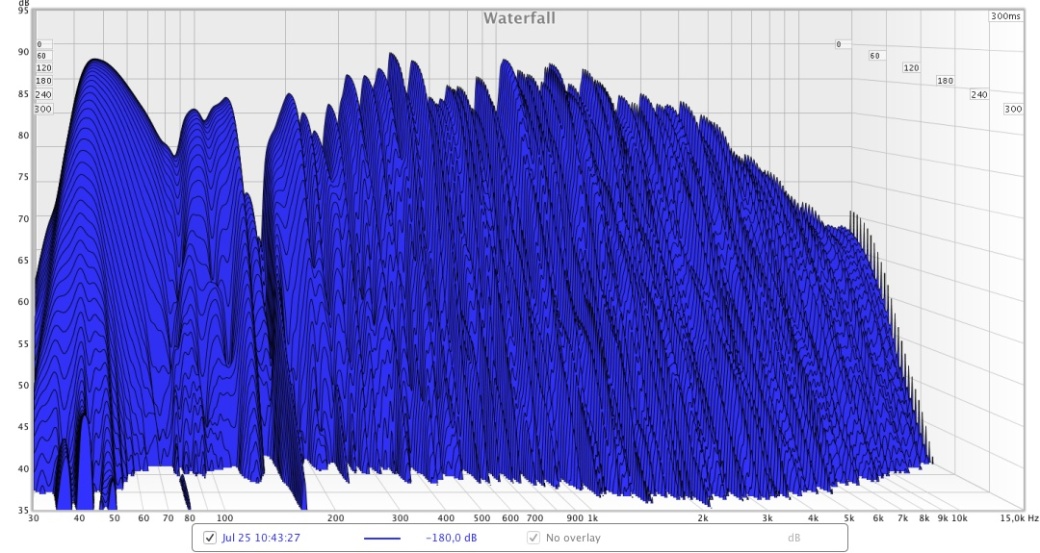
Waterfall diagram after installation of ER absorbers and couch

Spectrogram after ER treatment
Interestingly enough, the ETC shows now even more peaks. We will se how that develops with the next measurements.

In the next article I will describe how the ER absorber on the ceiling, i.e., the cloud absorber has been constructed and how mounting it changed the measurements again.
Thanks for sticking with me here and all the best,
Markus

Pingback: Building a proper control room – outline and prerequisites | orthogonalrecords
Pingback: Building a proper control room -construction of a cloud absorber | orthogonalrecords